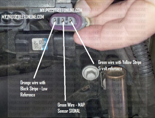
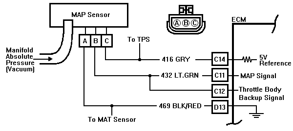
Map Sensor Diagram – A fully functioning MAP sensor is necessary to maintain the right combination of acceleration, fuel economy, emissions and engine smoothness. When the throttle is wide open and air is rushing into . An affinity diagram or map, is a tool that helps designers, researchers and project managers organize ideas, information, and observations to identify patterns and, ultimately, insights. Also known as .
Map Sensor Diagram
Source : www.youtube.com
MAP Sensor wiring colors | GMC Acadia Forum
Source : www.acadiaforum.net
Toyota map sensor pinout
Source : in.pinterest.com
GM 3 bar map sensor calibration G4+ Forums | Link Engine
Source : forums.linkecu.com
Alky kit with Dpe map sensor? CorvetteForum Chevrolet Corvette
Source : www.corvetteforum.com
MAP Sensor Wiring | Team Integra Forums
Source : www.team-integra.net
Sensors
Source : motorsport-electronics.co.uk
MAP Sensor Wiring Diagram: Learn How to Connect Your Car Sensor
Source : www.tiktok.com
MicroSquirt® Introduction
Source : www.useasydocs.com
Code 34 Manifold Absolute Pressure (MAP) Sensor Circuit
Source : fieros.de
Map Sensor Diagram MAP Sensor & Wiring Diagram YouTube: A manifold absolute pressure sensor (MAP) is one of the sensors used in an internal combustion engine’s electronic control system. Engines that use a MAP sensor are typically fuel injected. The . Map and search of GeoNet sensor networks that deliver high-rate-data. Use the date search filter to see sensors that were operating in the past. More detailed station/sensor information can be .


